|
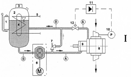
1.Manual Replenishment pump
2.Seal Pot
3.Level Switch
4.Sight Glass
5.Heating/ Cooling Element
6.Magnetically Driven Gear Pump
7.Safety Valve
8.Polymer Discharge Pump |
|
9.Double Mechanical Seal
10.Pressure Sensor
11.Control Electronics
12.Control Valves
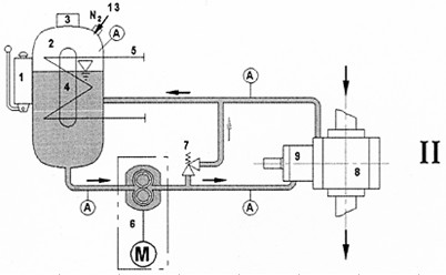
13.Nitrogen Connection
A =Process Pipe under buffering Pressure
B =Process Pipe under atmospheric Pressure |
|
System I (the dynamic system) is employed, when the pressure
on the suction side varies over a comparatively wide range. This is
measure by a pressure sensor (10) which regulates the control
valve (12), at the output of the rotating mechanical seal (9), via the
control electronics (11). Depending upon the position of the control
valve (12) the gear pump pumps the medium against the more or
less open control valve (12). A buffering pressure is built up, which
is always above the suction pressure of the Polymer pump (8).
This differential pressure is adjustable. With this system, the dyna-
mic buffering pressure is generated by the gear pump (6).
The pipelines under buffering pressure are marked with an “A”,
whilst those under atmospheric pressure are marked with a “B”.
The buffering medium tank (2) is in this case not pressurised. |
|
System II (the static system) is employed when the pressure
on the suction side of the pump (8) remains comparatively
constant. In this case, the buffering medium tan (2) is pressu-
rized, via the connection (13), using nitrogen. The buffering pre-
ssure is generated by the nitrogen. The gear pump (6) has only
to combat pipeline losses. In this case, the complete system,
including the buffering medium tank (2) is under buffering
pressure from the nitrogen. The manual topping-up pump (1)
can be used to raise the level in the buffering medium tank (2)
against the buffering pressure, when the level switch (3) indi-
cates that the level is too low. |